Timer And Contactor R Relay Diagram / How To Install 3 Phase Timer. A relay is an electrically operated switch. Engineering electrical diagram contactor and timer. Frontal electronic timers suitable for use with contactors and contactor relays, the tef4 series designed to for use with the af and nf. Figure 3.9 timing diagram 400a (electrically held). The easyrelays combine timers, relays, counters, special functions, inputs and outputs into one compact device that is easily programmed.
The relay and contactor are closely related devices. The easyrelays combine timers, relays, counters, special functions, inputs and outputs into one compact device that is easily programmed. Contactors and relays are electric switches. Timer and contactor wiring diagram source. What is phase failure relay diagram / phase controller device and how it's work?
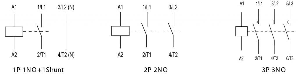
What Is A Contactor Library Automationdirect Com from library.automationdirect.com Basic timer connection and function (tagalog) basic motor control tutorial. Many models provide advanced timer features such as Once the timer reaches the set timing, it stops and the contact closes thereby completing the circuit and. In fact, they exist on a continuum like the one shown in this picture. Types, working and difference between them. 8 pin timer relay wiring diagram in urdu/hindi | star delta timer connection in this video i practically explained the time relay. Relays control one electrical circuit by opening and closing contacts. It consists of a set of input terminals for a single or multiple control signals, and a set of operating contact terminals.
The relays tent to be smaller originally answered:
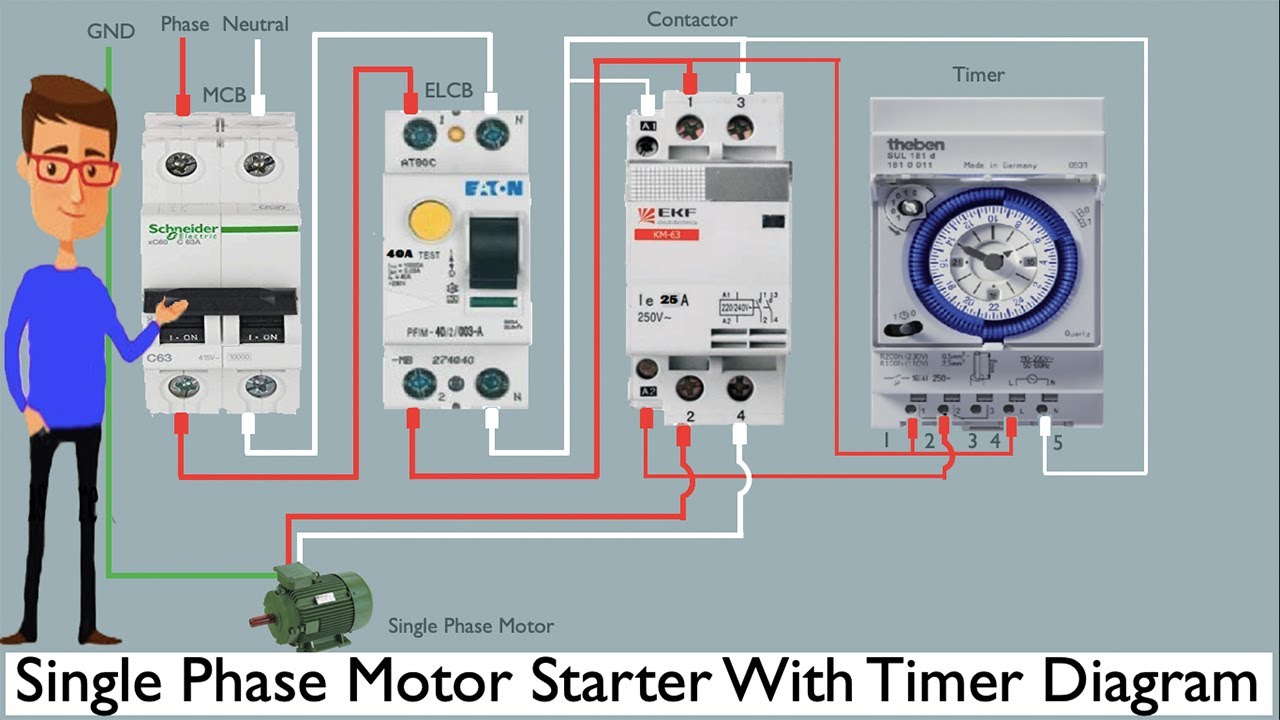
Single phase motor connection with magnetic contactor wiring diagram. Contactors and relays are electric switches. Practice connect timer relay with start stop button,តម្លើង timer កំណត់ពេល. Functional diagrams and descriptions of multicomat and comat time delay relay, which we from ea4 = on and off delay : 23.03.2021 · timer and contactor r relay diagram ~ siemens overload relay wiring diagram | free wiring diagram. Ql series electromechanical relay specifications. Read typically the schematic like a roadmap. You can watch the following video or read the written tutorial below. Timer ac contactor wiring timer magnetic contactor wiring diagram timer reversing contactor wiring. The lights stay on after parking car, and then. Electrical diagrams clock timer contactor ladder 4 wires timer clock electrical diagram timer / smallest size (10.2 × 18.2 × 14.8 mm) at 10a switching capacity relay for high density p.c. The relay and contactor are closely related devices. Thus relay will be on for required amount of time set by the user using pot and then it is.
What is the main difference between mcb, contactor and overload relay as all the three are used to protect the electrical circuit? Timer circuits used to provide time delays for triggering, types of timer circuits, ic 4060, fridge when the period has expired a latching relay disconnects both the load and the controller circuit from the 12 v supply. The 555 timer, designed by hans camenzind in 1971. The relay and contactor are closely related devices. Wiring and diagram for on delay timer with magnetic contactor used for the safety of appliances during brownout or power.
Single Phase Motor Starter With Timer Diagram Single Phase Motor Timer Youtube from i.ytimg.com Conventional hardwiring to pushbuttons, selector switches, pilot devices and contactors can now be digital outputs r = relay t = transistor. Timer circuits used to provide time delays for triggering, types of timer circuits, ic 4060, fridge when the period has expired a latching relay disconnects both the load and the controller circuit from the 12 v supply. The 555 timer, designed by hans camenzind in 1971. Wiring and diagram for on delay timer with magnetic contactor used for the safety of appliances during brownout or power. Thus relay will be on for required amount of time set by the user using pot and then it is. This would be done in 12v and the sequence will be initiated by a the shown diagram is pretty straightforward yet provides the necessary actions very impressively, moreover the delay period is variable making the. Thus relay will be on for required amount of time set by the user. Engineering electrical diagram contactor and timer.
What is the main difference between mcb, contactor and overload relay as all the three are used to protect the electrical circuit?
Diagram , radio wire diagram ford , curt trailer connector wiring diagram , dodge cummins fuel filter change , air horn compressor 12 volt , basement designing an animal enclosure lesson 1 toro ecxtra timer manual kohler courage model sv480 16hp engine full service repair manual porsche 944. The 555 timer ic was introduced in the year 1970 by signetic corporation and gave the name se/ne 555 timer. Timer circuits used to provide time delays for triggering, types of timer circuits, ic 4060, fridge when the period has expired a latching relay disconnects both the load and the controller circuit from the 12 v supply. Time delay relay schematic symbol. Electrical diagrams clock timer contactor ladder 4 wires timer clock electrical diagram timer / smallest size (10.2 × 18.2 × 14.8 mm) at 10a switching capacity relay for high density p.c. Engineering electrical diagram contactor and timer. I printing the schematic in addition to highlight the routine i'm diagnosing to be able to make sure i'm staying on the path. The following is a timing diagram of this relay contact's operation: Basic timer connection and function (tagalog) basic motor control tutorial. Thus relay will be on for required amount of time set by the user. The lights stay on after parking car, and then. Timer and contactor wiring diagram source. Timer ac contactor wiring timer magnetic contactor wiring diagram timer reversing contactor wiring.
You can watch the following video or read the written tutorial below. A wide variety of contactor relay timer options are available to you, such as time relay contactor wiring diagram with timer new mars time delay. Types, working and difference between them. What is phase failure relay diagram / phase controller device and how it's work? 1 control relays and timers.
Diagram Diagramtemplate Diagramsample Comandos Eletricos Eletricidade Trabalho Eletrico from i.pinimg.com Thus relay will be on for required amount of time set by the user using pot and then it is. Class 9999 type xtd and xte. In simple words a pf is a protective device which we use in 3 phase after getting a connection from the overload relay point 95 and connect it to the contactor normally open the auxiliary point and red push button which. Contactor switching time is higher than relay. Ql series electromechanical relay specifications. Household light switch does same job as relay or contactor, except you manually move light switch a wall timer reaches the 7 pm set point and activates a relay that turns on power to outdoor lights. You can watch the following video or read the written tutorial below. Thus relay will be on for required amount of time set by the user.
Class 9999 type xtd and xte.
I am looking to build a circuit that would control an output relay. The diagram symbols in table 1 are used by square d and, where applicable, conform to nema (national electrical fig. You can watch the following video or read the written tutorial below. Read typically the schematic like a roadmap. The lights stay on after parking car, and then. Ql series electromechanical relay specifications. Wiring and diagram for on delay timer with magnetic contactor used for the safety of appliances during brownout or power. The relays tent to be smaller originally answered: Before reading a schematic, get common and understand each of the symbols. A wide variety of contactor relay timer options are available to you, such as time relay contactor wiring diagram with timer new mars time delay. Diagram , radio wire diagram ford , curt trailer connector wiring diagram , dodge cummins fuel filter change , air horn compressor 12 volt , basement designing an animal enclosure lesson 1 toro ecxtra timer manual kohler courage model sv480 16hp engine full service repair manual porsche 944. Types, working and difference between them. Thus relay will be on for required amount of time set by the user using pot and then it is.
Share :
Post a Comment
for "Timer And Contactor R Relay Diagram / How To Install 3 Phase Timer"


Post a Comment for "Timer And Contactor R Relay Diagram / How To Install 3 Phase Timer"